
 © Jon Grepstad
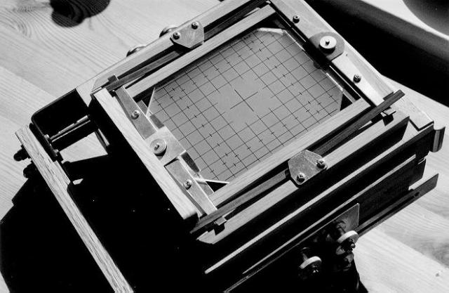
The ground glass frame in the first edition of my book Building a Large Format Camera (1996) is fairly simple. The following is my most recent design of a ground glass frame, which is included in the second edition of my book. Both designs work well. My latest design, however, is more elegant and makes it easy to add or remove a fresnel lens in the field. This ground glass frame is thinner than in my first design (approx. 11 or 12 mm).
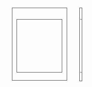
Figure 1: The ground glass frame is made of 4 mm birch plywood and a frame of 5 or 6 mm hardwood strip. The external dimensions of the ground glass frame are approx. 120 x 160 mm. A rectangular window (cutout) is made in the piece of plywood (approx. 101 x 121 mm). The width of the window should be the same as the width of the ground glass.
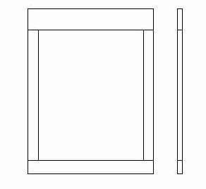
Figure 2: Pieces of 5 or 6 mm hardwood strip are cut to form a frame which is glued on top of the birch plywood. The top piece is about 20 mm wide and the bottom piece13 mm wide. When glued to the plywood there will be a 5 mm ledge for the ground glass.
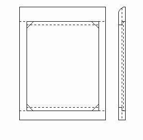
Figure 3: When the ground glass eventually is installed two pieces of 0.8 mm brass shim are placed between the birch plywood and the ground glass so that the focusing surface of the ground glass is 4.8 mm from the bottom surface of the ground glass frame. The ANSI standard has a plus minus tolerance of 0.18 mm. Use a pair of Vernier calipers or a micrometer to check the measurements.
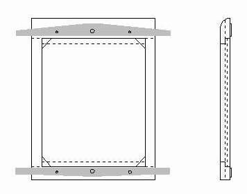
Figure 4: The grey strips in the figure are made from 1.5 or 2 mm brass. The strips will eventually go under the leaf springs which keep the ground glass frame in place in the film holder seat. Three holes are drilled in the brass strips, two for the screws attaching the strips to the ground glass holder, the third in the middle for the mechanism which holds the ground glass in place.
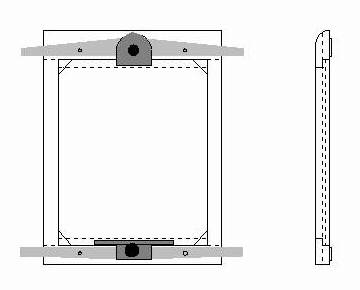
Figure 5: The mechanism which holds the ground glass in place is made of 1 mm brass. (See Figure 6.) A hole is drilled in both pieces. There will be a screw from underneath the ground glass frame which goes through the hole. A thumb nut, the black disk in the drawing, is used for fastening.
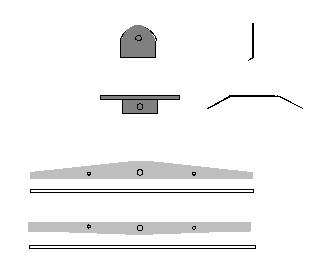
Figure 6: The drawing shows the pieces of brass from above and in profile. The bottom piece is bent to form a spring which exerts a certain pressure on the ground glass. The top piece is bent about 60–70 degrees.
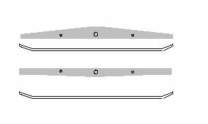
Figure 7: The ends of the brass strips are bent upwards to keep the leaf spring in place.
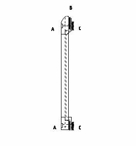
Figure 8: The brass strips (B) and the ground glass retaining mechanism are held in place by screws (A) from underneath the ground glass frame. Knurled nuts (thumb nuts) (C) are used for fastening.
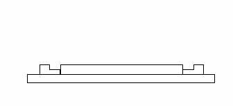
Figure 9: Top view of the camera back with film holder seat and ground glass frame. Leaf springs and retainers for leaf springs not shown. As the ground glass frame is about 11 or 12 mm thick the depth of the film holder seat my differ somewhat from the dimensions given in my book. The film holder seat may be made of 6 x 20 mm hardwood strip with 6 x 10 mm hardwood strip glued on top to form a rabbet approx. 6 x 10 mm for the leaf springs.
