
In an email Jean d’Avignon in Toulouse, France, writes:
Here are a few images of a 4×5 I’ve recently constructed.
I built my first 4×5 monorail camera back in 1982-83 while I was studying at Ryerson (Toronto Ontario). It was built of cherry wood and was similar to your design.
In 1987, during my graduate studies at Concordia University (Montreal Quebec), I built a flatbed 8×10 camera whose design was inspired by the Deardorff 8×10 field camera. I had worked with such a camera while I was at Ryerson. It’s built of cherry and maple wood.
While I was at Concordia I also cut and prepared the wood for the construction of a second 8×10 field camera (not yet assembled) as well as a 4×5 field camera.
I recently recovered what I had left back in Canada for all these years and so this summer I assembled the 4×5 camera. I guess that by this time, 25 years later, the wood had sufficient time to dry !!
I have no plans for this camera, everything is built around a standard 4×5 film holder (my starting point) and I designed and built the different parts as I went along. I did however have a very good idea of where I wanted to go and made corrections to allow for tight tolerances as I went along.
Materials: Cherry and mapple wood, stainless steel, aluminium, knurled nuts are radio buttons bought in Montreal in 1985 at an electronics shop, uni-directional and woven carbon fiber, epoxy resin, rubberized bellows material (bought at Turbigom Paris years ago), ground glass.
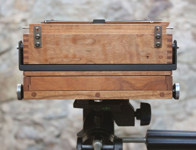
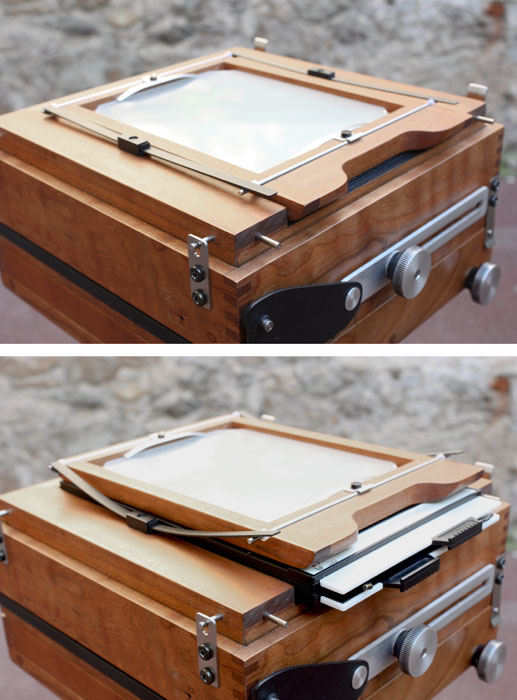
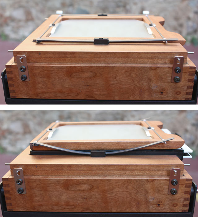
Rear view folded.
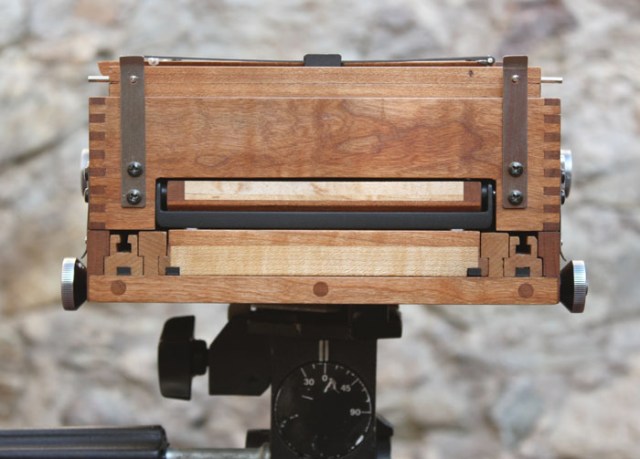
Front view folded.
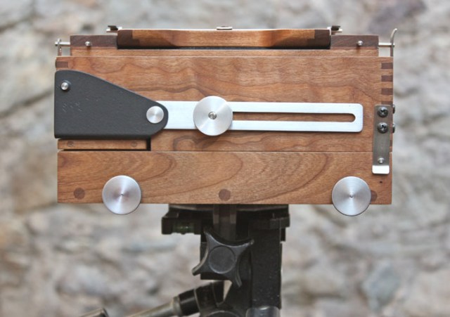
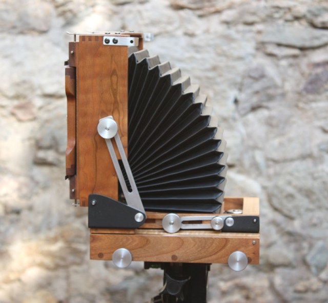
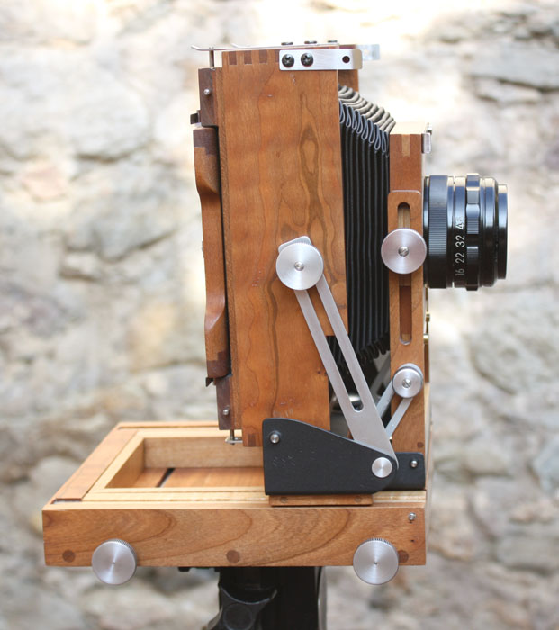
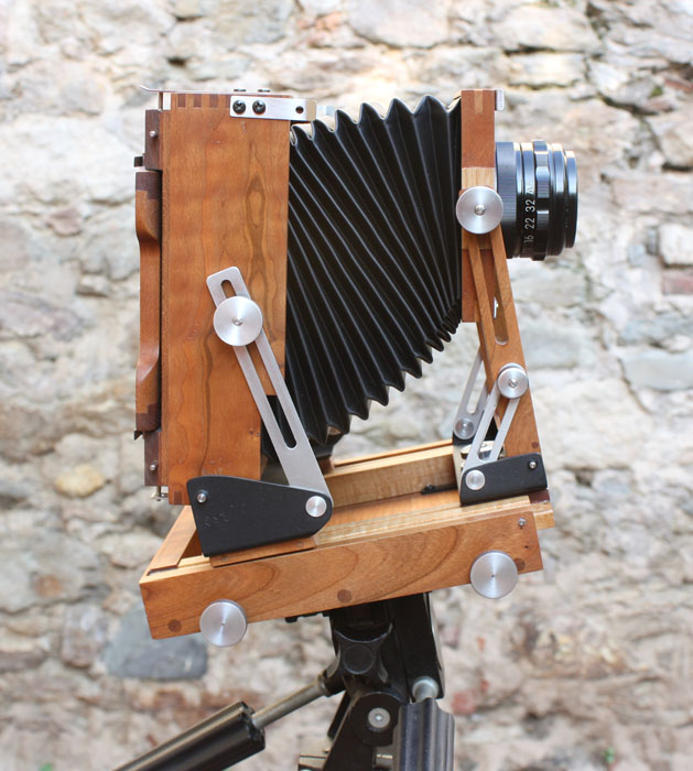
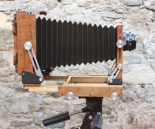
Side view folded.
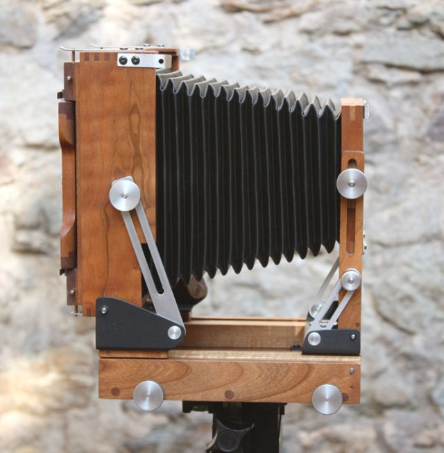
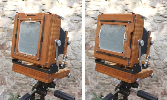
Unfolding the rear.
Unfolding the front.
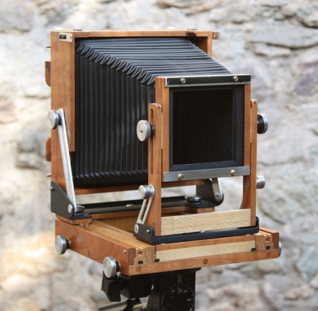
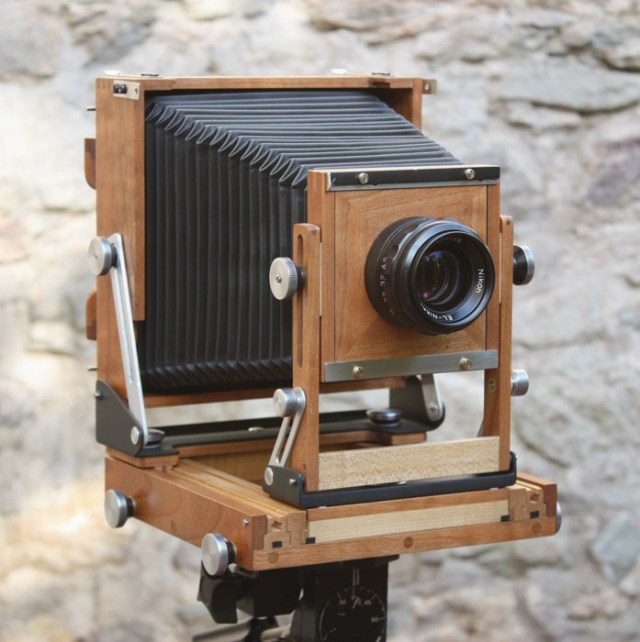
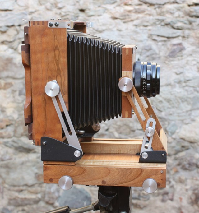
Perspective view, the cradles for the front and rear standards are made of multi directional (non woven) carbon fiber–epoxy resin composite and painted black. The wood has two coats of oil plus one coat of hard wax (car paste wax). On the inside the wood is stained black with three coats of black ink.

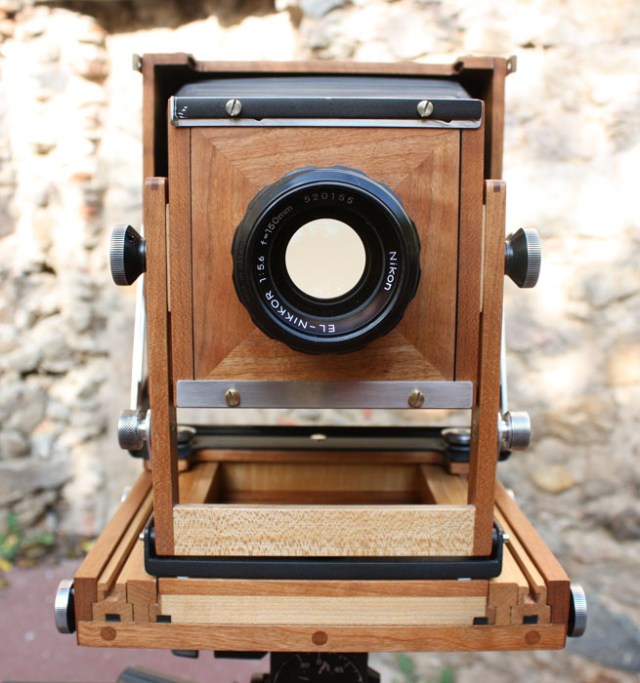
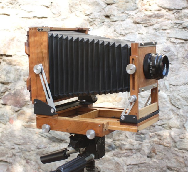
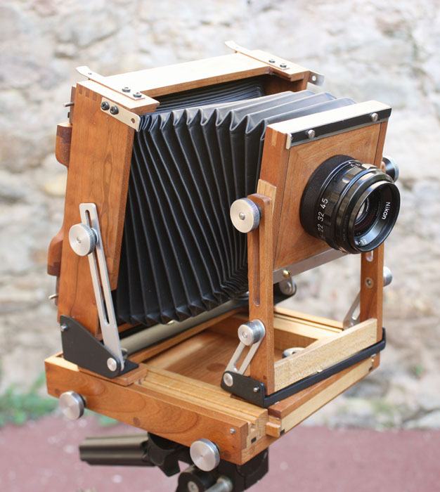
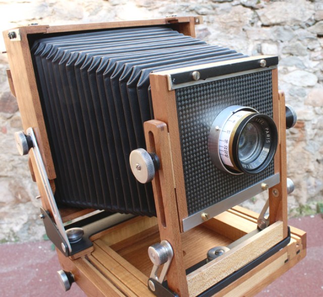
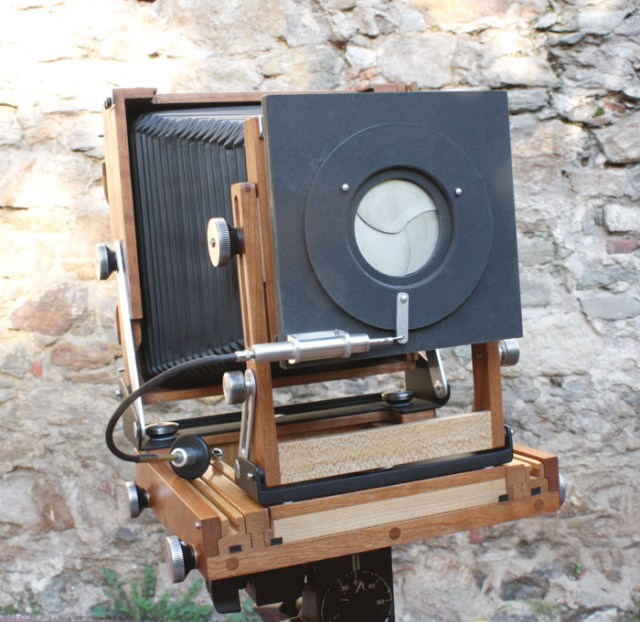
Perspective view with 150mm Nikkor enlarging lens (it covers and works quite well even focussed at infinity).
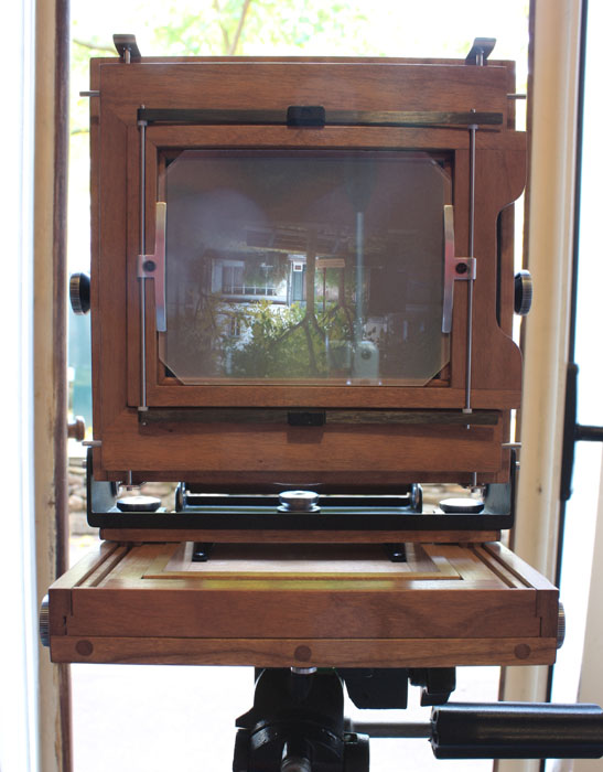
Front view unfolded.
This is not quite maximum compression, with the front angled back I can gain about another 2 or 3 cm.
Partial foreward extension.
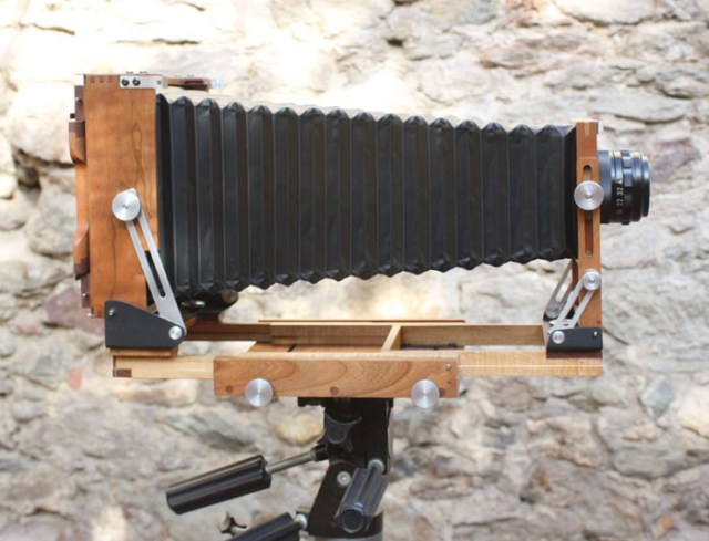
This is about maximum extension and is limited by the lenght of the bellows, note that had I built longer bellows the camera base itself could probably support another 4 or 5 cm of extension.
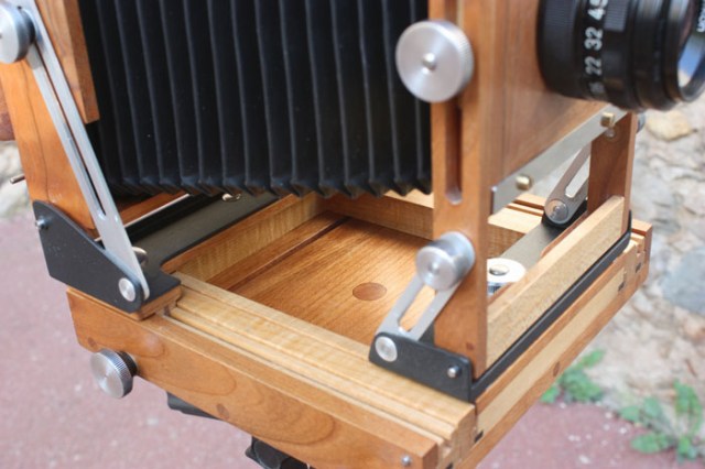
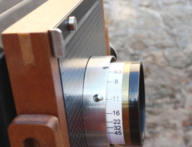
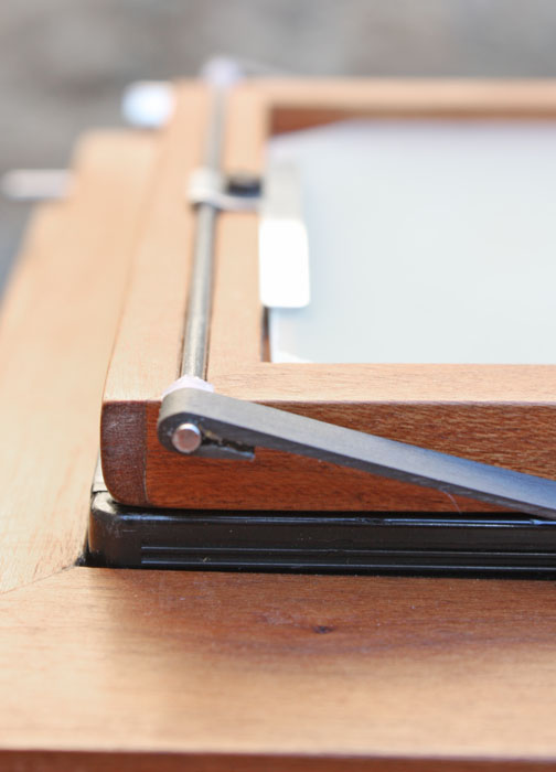
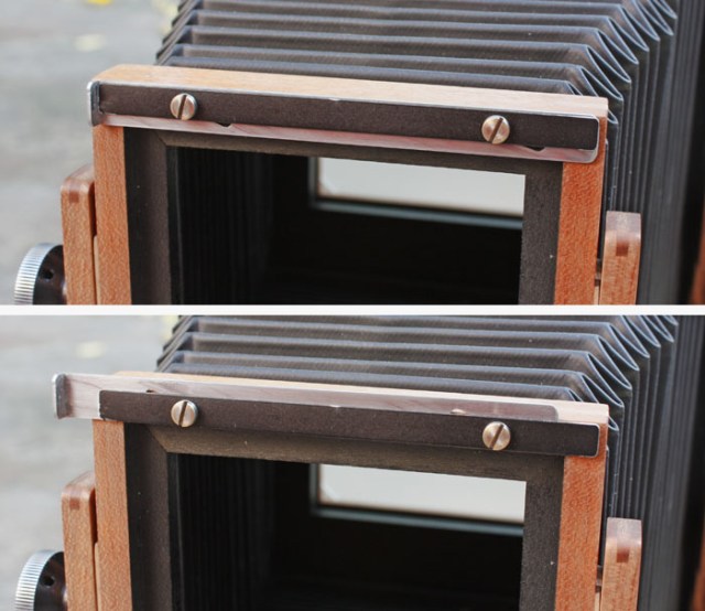
Detail.
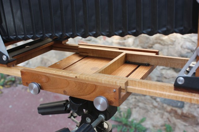
Detail extended.
The rear frame can rotate allowing for portrait or landscape composition.
Swings front and rear, rise and fall, tilts.
Typical (architectural photo) rise using combined movements (the 150 can’t cover with this amount of movement).
Partial rear extension.

Combined mouvements (fall).
Detail.
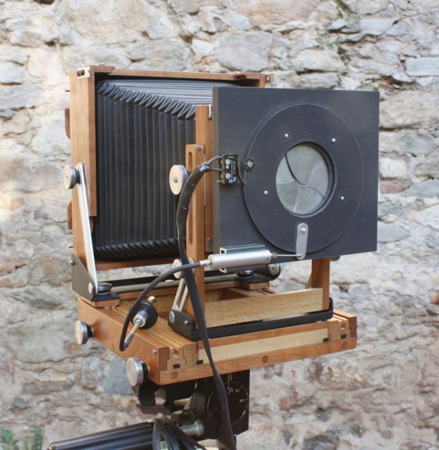
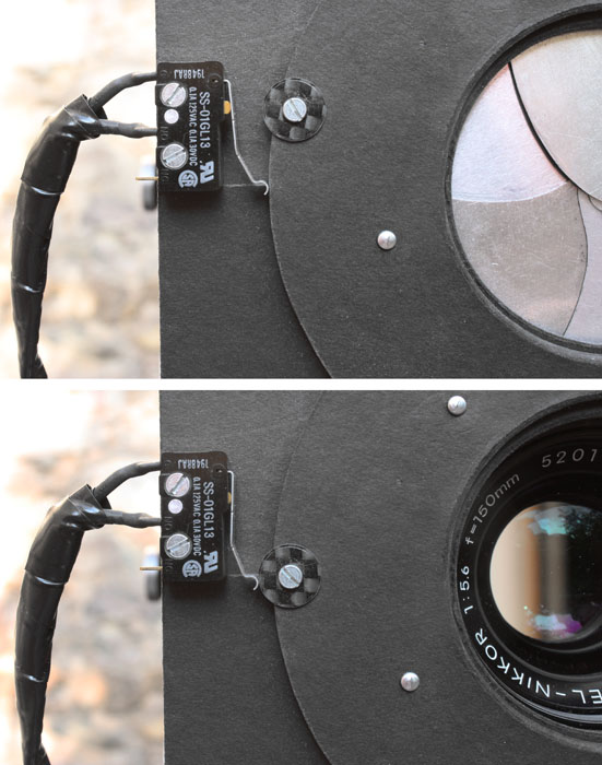
I designed and built my own leaf shutters out of mat board and aluminium. These are of course best adapted to long exposures although you’ll notice that on the 150 lens I’ve added a syncro flash switch which is set off when the shutter is wide open.
Tripping the shutter.
Tripping the shutter detail.
The cartridge (at the bottom left of the photo) contains a spring loaded piston activated by the shutter release. I think I can do ¼ of a second and I’m sure I can do ½ second repeatedly with a little practice and concentration.
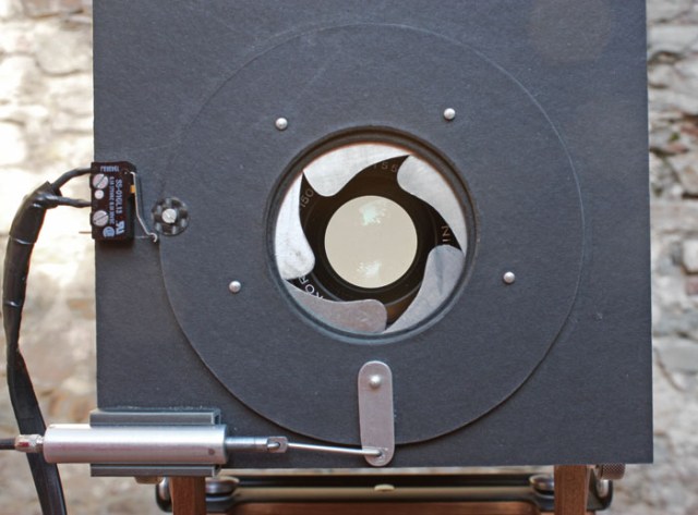
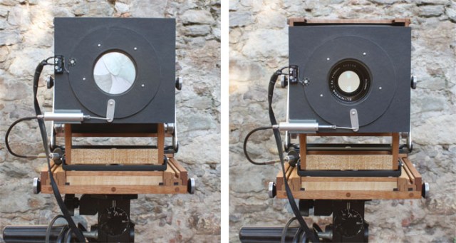
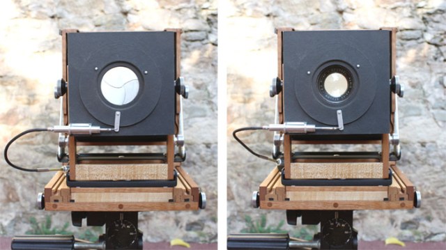
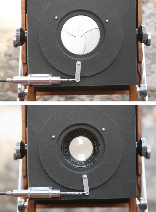
Detail of the 5 leaf shutter half open.
A modified Roussel Stylor 180mm lens from an old 5×7 camera. The lens is mounted on a composite lens board made of woven carbon fiber and epoxy resin.
Detail of Stylor lens.
Perspective view with Stylor lens and a three leaf shutter.
Tripping the shutter.
Tripping the shutter detail.
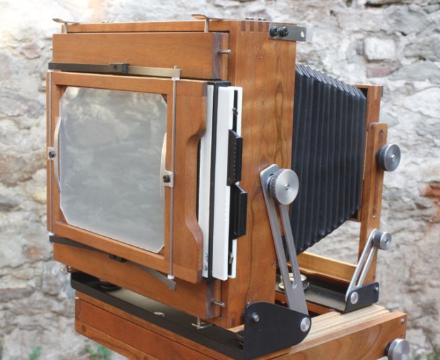
Perspective view rear with negative holder in place.
I made the springs on the ground glass frame (pressure frame for the negative holder) out of uni-directional carbon fiber and this works exeptionally well as compared to other metal spring material that I’ve used on other cameras.
Making a ground glass is quite easy, the recipes are out there on the web but here are a few extra ideas.
You can find 2mm thick glass in some cheap picture frames (I preffer 2mm rather than standard 3mm glass found in hardware stores).
Years ago I bought a peice of ground glass in a hardware store, not a good idea, it was so coarse that it was unusable.
If you can’t find grinding paste or powder you can simply take the grit off of standard sandpaper or emery cloth (just as long as it’s not wet sand type paper). The adhesive for the grit on standard sand paper is water soluble, simply put the peice of paper in water for a few seconds and take it out, give it a little time for the adhesive to disolve and then scrape off the grit with a blade or a spatula. Experiment with different papers to find the grit you need. I’ve used this technique with success.
The position of the ground glass is critical in order to establish proper focussing, it needs to be exactly on the plane as that of the film when the film holder is inserted. A way of doing this is to make the frame so that the glass ends up a little bit more foreward than it should be and then to use shims to position it perfectly when the camera is finished. Shimming away the ground glass to its proper position is easier and more precise than getting measurements dead on on a table saw. It also allows for variations which occur at the finishing stages (ie. sanding the wood to a smooth finish). Shims can be made of different materials, aluminium or steel from beer cans are my favorites, paper or mat board will also work.
Detail.
Detail.
Spring detail.
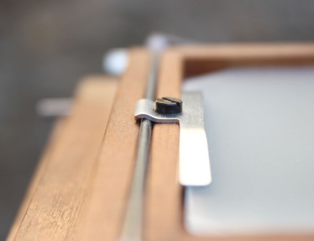
Pressure clip for the ground glass.
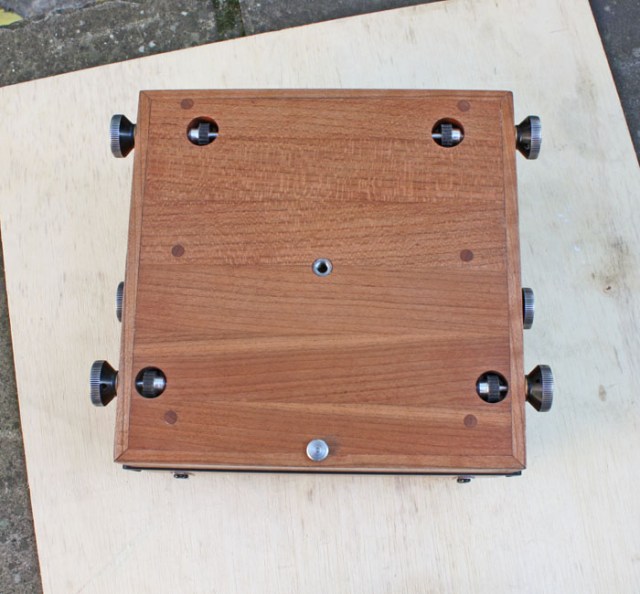
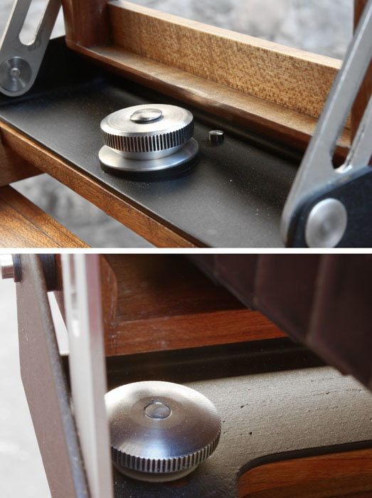
Underside.
Underside knob and pinion.
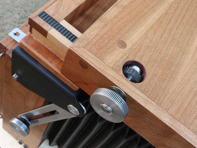
Underside detail partial rear extension.
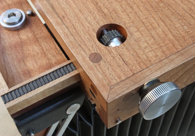
The racks and pinions (for focusing) are home made of carbon fiber (racks) and aluminium and rubber belts (pinions). I had a few cogged belts lying around that I’d taken out of discarted printers. I did a carbon fiber moulding of the belt which became the racks and then wrapped and glued a small lenght of this same belt around aluminium cores of precise diameter to become the pinions. Although belts are geometrically designed to work around cogged pulleys and not the other way around, this solution worked very well for me. I did this because I couldn’t easily find commercialy available brass or plastic micro racks and pinions.
Detail front rack and pinion.
Detail lensboard retaining clip.
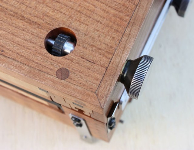
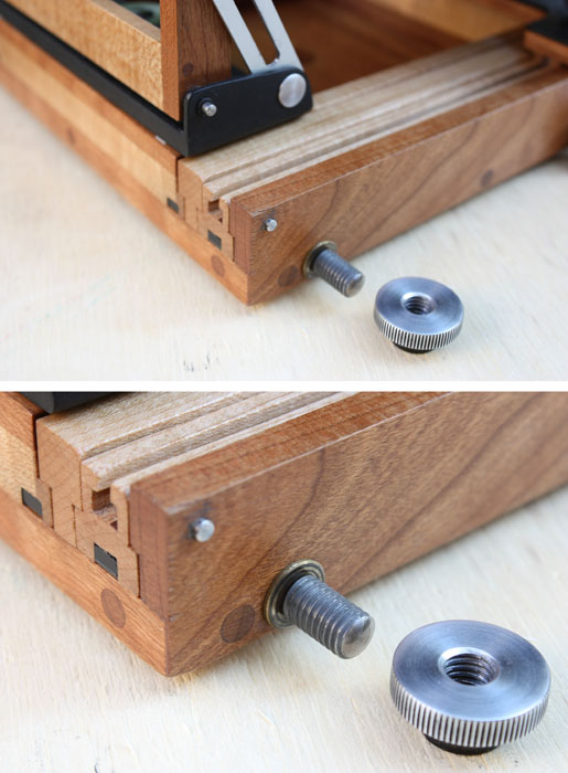
Detail of front and rear lock nuts.
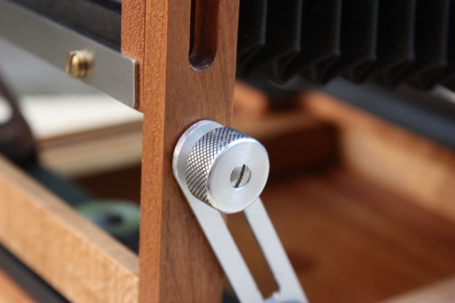
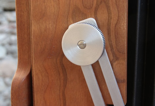
Focus locking mechanism.
Front detail.
Rear detail.
View with 150mm lens.
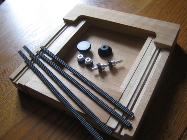
Prior to assembly, racks and pinions, camera base.
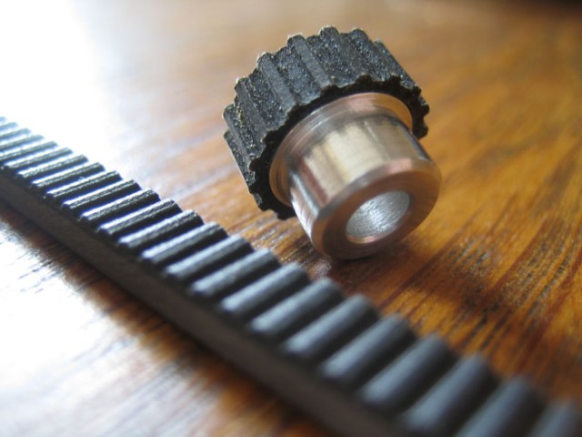
Rack and pinion detail.
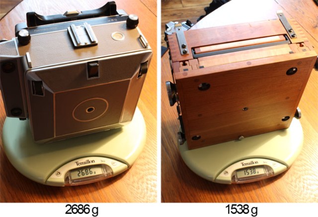
Weight comparison with a Linhof Technika IV. Both cameras are without lens.
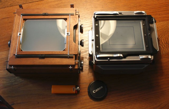
Size comparison with a Linhof Technika IV.
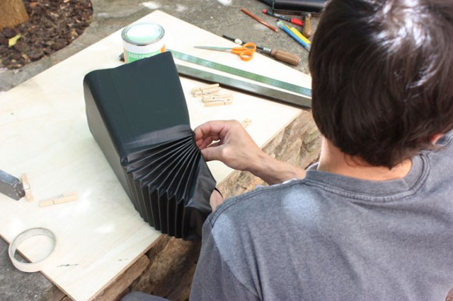
Making the bellows. I’ve always found that making bellows is a pain. For this camera I made them twice due to an error in measurements.
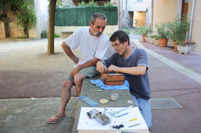
Working outside under vigilant quality control.
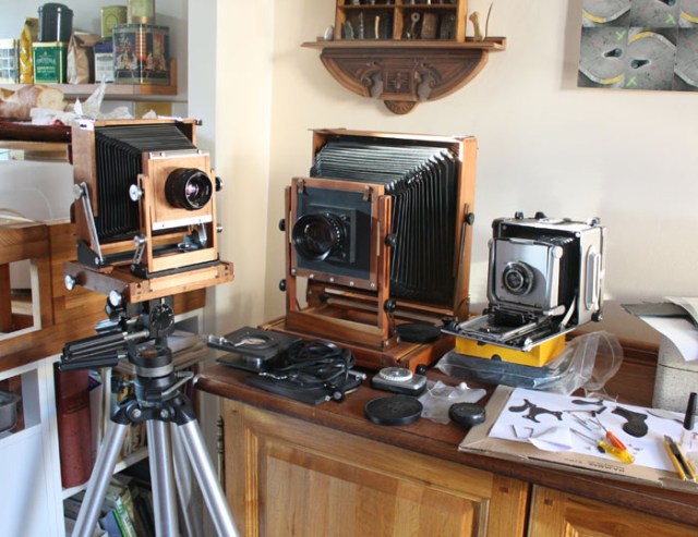
Left to right: 4×5 folding field camera 2011, 8×10 folding field camera built in 1987 with a modified 270mm apo-gerogon S (now opens to about f8 rather than its rated f11, has enormous coverage), 4×5 Linhof technika IV circa ~ 1957 with a 105 Steinheil lens which doen’t quite cover at infinity.
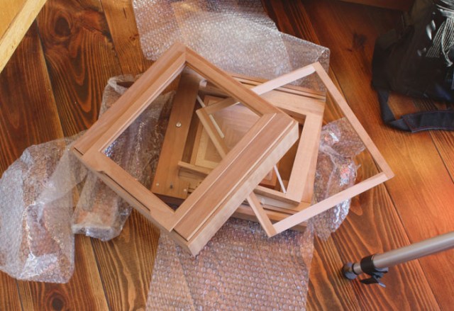
Here is the wood for another 8×10, cut and glued 25 years ago. I still need to make all the fittings and everything else.
5 March 2012.
